Pressure Grouting of Voids Under Machinery Bases
While earlier issues of the Grouting Technology Newsletter have dealt with how to install grout properly, this issue will tell you how to fix a particular problem that can occur: that of voids under a machinery base plate or pump base.
Such voids do occur from time to time, either because of improper grouting techniques, actual shrinkage of the grout or, in rare cases, because of movement of the machinery base. Filling such voids to restore or achieve good base-plate contact can turn a poor grout job into a successful one.
The filling of grout voids under machine bases with liquid epoxy grouts is a proven concept that has been used since the late 1960’s. Using injection ports and vent holes to expel trapped air, a liquid "shim" of epoxy grout, as strong as the grout below it, is pumped or gravity fed into the void. Upon curing, the liquid epoxy becomes hard and fills the cavity, providing support at machine pedestals and can reduce vibration in adjacent plate sections.
Description
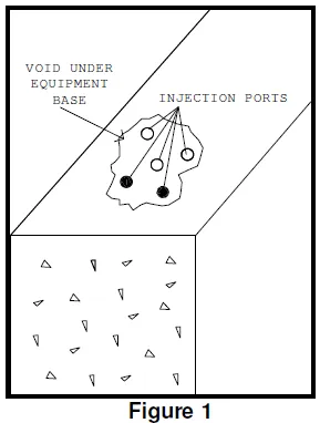 Once the extent of a void is determined, holes are drilled into the cavity. A small void may only require one injection point and one vent point, but typically a "five-spot" layout is required, with four injection ports at the corners and a vent port in the center. Multiple "five- spot" layouts may be required for a large void since the distance between holes should not exceed 12" to 14". (See Figure 1). Holes may be drilled vertically if access from above is available or at an angle or even horizontally depending on the equipment configuration.
After drilling the initial hole or holes into a void, the depth of the void can be determined by measuring the penetration of a stiff wire. Additional holes can also be drilled to confirm the extent of the void. If the depth checks indicate consistent voids of over 1/4” in thickness, then a filler will need to be added to the normal two-part liquid epoxy injection grout. A three-part formulation may even be required if the depth can be measured in inches which, in turn, will require larger 1" injection holes.
Warning
Two-part liquid epoxy injection grouts are designed to fill thin voids. Filling a deep hole, say 10" deep, where the volume would require over a gallon of liquid epoxy grout would be very dangerous as the heat developed could cause distortion of the equipment base. Severe ruptures of the equipment resulted on one project where a 14" deep void was filled with only three gallons of a two-part liquid epoxy grout. The filler of silica used in three-part epoxy grout systems reduces the heat generated, so such formulations can be used where deep pours are required.
In addition to the above precaution, eye protection should be worn by the applicators and helpers to guard against a pressure leak squirting the epoxy mixture into the eyes. All general safety precautions should be followed for using epoxy grouts.
Equipment Description
Usually holes are drilled and tapped for 1/8" pipe fittings. (See Figure 1). When using two-part liquid epoxy injection grouts, all holes, both injection and vent, are tapped so a vent hole can also be used as an injection port during the final topping-off check. Common grease fittings with 1/8" pipe threads are used as a means of attaching the pumping mechanism, typically a handheld grease gun, to the injection port.
Mixing
Mixing of the two-part injection grout should be done in small batches. Small batches are required, not only because of the short working time (pot life) of two-part epoxies, but also because of the small capacity of the injection (grease) gun. Be sure to accurately measure out the "A" and "B" components when splitting the particular product's shipping unit, to be certain the mixture will harden properly. Adequate crew size and proper job planning are essential since the injection process on any one piece of equipment should be a continuous process; multiple voids may actually connect. Simultaneous injection with multiple gun operators may also be required depending on the complexity of the problem.
Application
When grease guns are used, the end cap and spring plunger are not used, and the grease gun is held vertically. A helper is required to fill the gun through the open top as the liquid is being pumped. It is important that the gun always have some liquid level above the plunger so air is not inadvertently injected.
Large repair projects, where there may be over 30 injection ports or the need to pump over two gallons of liquid epoxy grout at a time, can be more efficiently handled by a paint pressure pot and hoses, rather than hand-held grease guns. Up to two hoses with trigger guns can be used with a two-gallon pressure pot if an air compressor is available.
With either type of pumping equipment, care should be taken to see that if pressure is applied to an unvented cavity, the pressure under the equipment is limited to 25 to 30 psi to prevent inadvertent deformation of plate sections. As an added precaution, the ball check in the grease fitting can be removed or the fitting temporarily removed from the vent hole. Either type of injection equipment needs to be compatible with epoxy cleaning solvents and cleaned frequently. Hardened liquid epoxy injection grouts will ruin either type of pumping equipment.
Injection should start at one of the outer ports and continue until material comes out of the open vent holes. As pumping is started, resistance will be felt by the operator as the void fills. Pumping should be stopped for one to two minutes to allow the pressure to subside as the epoxy mixture flows into restricted voids. Alternately start and stop pumping until the void is full and a return shows at the vent hole. Sometimes it is necessary to move on to adjacent injection ports if the void is severe. The goal is to fill the void sufficiently so that injection at every outer port causes flow to be seen at the vent port or ports.
When satisfied that the void is full, all fittings should be removed and the liquid level in all holes monitored until the grout sets. In case of slow leakage into an adjacent void or into a foundation crack, additional pumping can be resumed. If leakage continues, the grout may have to be allowed to set and then a second operation applied either through the original holes or new holes. Experience and common sense are needed under these circumstances.
While the above may sound complicated, numerous pump and compressor bases have been satisfactorily repaired by injection of liquid epoxy shims. Skilled contractors and service representatives are available to assist on complicated projects.
Figure 2
Hole Drilling
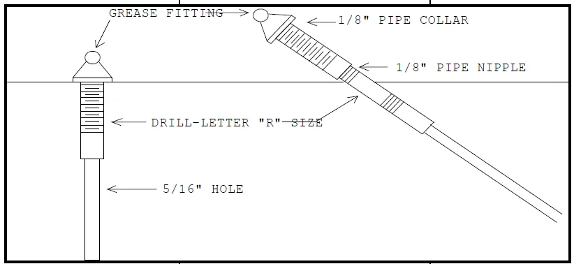
- Drill hole in plate deep enough for threaded length of 1/8" N.P.T. grease fittings. Use a Letter R Drill. Depending on the type tap to be used, up to 1 1/2" of R drill size hole may be needed to get adequate full depth threads for the grease fitting.
- If the drilled Letter R size hole is not through the plate into the void, then the hole size can be reduced to 5/16" as an option.
- Tap hole - 1/8" N.P.T., being sure to tap deep enough to get sufficient full depth threads if using a tapered pipe tap.
- Where an inclined hole is necessary to reach the void, good threads in the Letter R size hole will not be made in the upper section of the hole, so drill and tap deep enough to insure good thread contact. A 1/8" pipe nipple extension will reach good threads, although counter boring the upper section can also be done. Add a 1/8" pipe collar to the pipe nipple and then add the grease fitting.
Home > Newsletters > Pressure Grouting of Voids Under Machinery Bases

