Anchor Bolts – The Forgotten Connection
For several years, strict attention has been paid to good grouting materials and installation techniques, particularly with the development of epoxy grouts. In more recent years, the vital role of anchor bolts is being recognized as just as important as the grout under the machine. An analysis of the part each plays points out that they really are equal partners. It is the function of a good machinery grout to provide a strong, stable bed for the machine base or sub-base, such as a soleplate and chock. The base should remain at a precise elevation within .001” over the life of the machine. The grout prevents any downward elevation changes. The anchor bolt prevents the machine base from moving upward. Upward deflections are just as harmful as downward deflections, so the anchor bole and its proper maintenance (as will later be discussed) are every bit as important as the grout.
What Constitutes a Good Anchor Bolt?
Fortunately, there are excellent ASTM specifications that detail various strength bolting systems; that is, the bolt or stud, the nuts and the washers. This makes it easier to know that you are getting an anchor bolt system that will provide the design load capability.
We will later discuss how the actual design load is calculated. Knowing what the load is will allow you to choose a bolting system made from 60,000 psi steel as specified in the ASTM A307, or a higher strength steel (such as B7) of 105,000 psi strength, as called for under ASTM A193.
Since the size hole in the equipment through which the anchor bolt must fit has usually been decided by others, choosing a stud of a higher strength specification is often the only way that a proper design load or holddown capacity can be achieved. When upgrading old anchor bolts, which is discussed at the end of this article, the use of a replacement bolt of higher tensile strength allows for the correction of an inadequate hold-down system.
Because of the importance of the anchor bolt and the damage it can cause if it breaks, choosing a bolt from a vendor who manufactures to ASTM specifications is extremely important. Be sure the nuts and washers are also made to the appropriate ASTM specifications.
While the strength of the steel itself is important, there are several other things that must also be taken into account. These items, which we will call "enhancements," can improve the bolt's performance dramatically.
For instance, it is a well known fact that a sharp notch in a steel member causes a stress concentration point which will fail first under heavy loading. Since cut threads are nothing but a series of sharp notches, the use of rolled threads has been found to reduce failure in the threaded portion of a bolt or stud, which is where they almost always fail. In fact, ASTM A193 calls for rolled threads which is one reason a bolting system made to A193 specifications can take greater loads.
A further enhancement to augment the use of rolled threads is to have the threaded portion, as well as the shank, shot peened to an appropriate specification, such as Mil Spec. No. S-13165-C. This reduces any stress on the surface of the steel from machining or rolling and is an extra factor of safety. Almost all critical fasteners used by the military and the space program are shot peened to get the highest strength and performance possible. Shot peening can also reveal a poorly rolled thread!

An off-center load occurs when an anchor bolt is not perfectly straight, or becomes slightly off-center when a long engine grows thermally. This causes the nut to apply an unequal load to one side of the bolt or stud. Self-aligning steel washers, consisting of matching concave-convex surfaces and made of steel (see Figure 1) matching the hardness of ASTM F436 (if used with a A193 specifications bolt), allow the offcenter line load to be corrected; an inexpensive solution to a vexing problem. An alternative is to use a single concave washer and machine the nut to match. However, this means altering a nut made to a strict ASTM specification such as A194 (2H nuts), so the nut may no longer meet that specification.
Now we come to an enhancement that embodies a concept often very hard to understand. This is the frangible section or a section that has been machined to a lesser diameter than the original bolt diameter. (See Figure 2). While not always applicable, there are times when a frangible section will enhance the performance of a bolt. Perhaps the following example will put this in better perspective.
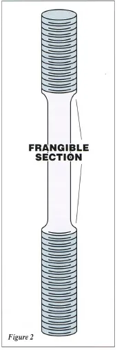 If a 1½" diameter bolt is being used where the clamping force it exerts is only 20,000 lbs. and the bolt is made of high strength steel conforming to ASTM A193 (B7-4140 heat treated), the anchor bolt would only be loaded to 13% of its total carrying capacity. A 1" bolt, made to the same specification and also loaded to 20,000 lbs. would be loaded to 31% of its capacity.
It is a quirk of bolting that the more lightly loaded 1½" bolt is more likely to break than the 1" bolt.¹ Bolts need to be loaded to at least 50% of their capacity in order to get enough stretch to keep the nut from backing off. Because of equipment limitations, if for some reason a higher load, say of 50,000 lb. clamping force, can't be used, then a reduced cross-section or frangible section is one way of compensating for this. It seems strange to remove good steel, but there are times when it makes good sense.
PreLoad
Preload, as its name implies, is the load that is put into a bolt as it stretches while being tightened. The preload plus the static weight of the equipment add up to give the total clamping force at each anchor bolt. The clamping force has to be high enough so that the downward holding force always exceeds any upward force the machine creates. It also must clamp with enough force so that the friction resistance to a horizontal load will prevent sideways movement. The higher the clamping force, the greater the resistance to lateral movement.
 The old rule of thumb was that the total clamping force should equal four times the equipment weight. Dividing by the number of anchor bolts gives the clamping force each bolt must exert, and from that the preload can be easily calculated by simply subtracting the proportionate of the equipment weight.
While the above calculations are important in deciding the proper preload, they also are used to size epoxy chocks, which are typically limited to a load of 500 psi, and steel or machined solid composite chocks that are designed to 1000 psi/1200 psi load. With studies in the machine tool field indicating chock loading of even up to 2000 psi is a better conductor of forces from the machine into the concrete foundations, quite possibly the gas compressor industry also will go to higher bolt preloads.
From the above, it can be seen that the design preload, often overlooked in the past, is a very important consideration. A corollary to this is that knowing the preload in the field is also very important. It is important to have gas in a car but also important to know how much.
In the past, when a new compressor engine was installed, the anchor bolts were simply tightened, often with a box wrench and sledge hammer. While the bolt was "tight," how tight was not known. As pointed out above, less tightness can be worse than too much tightening, up to a point.
Later it became field practice to use a torque wrench, which does give an approximation, maybe ± 20% of what the tensile load actually is, if a good conversion chart is used.¹ This is still a big improvement and is the most popular method of measuring the tightness of a bolt today because of its low cost.
Because a torque wrench is not the most accurate way of measuring the actual tension load, other methods are used as well but certainly not to the extent of torque wrenches.
Other methods are:
- ultrasonics
- load washers (strain gauges)
- crushable washers precalibrated for a set load
- measuring the change in length of the bolt as it is stretched by tightening
- turn of nut method
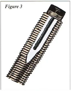
- patented load monitor called “RotaBolt™” (See Figure 3).
The latter is probably the most economical, practical method of the several alternatives to a torque wrench, since any loss of tension can be detected by trying to turn by hand the RotaBolt™ cap. However, no matter what method is used, checking the tightness of the anchor bolts for loss of preload in conjunction with crankweb deflection checks should be a part of regular maintenance. More recent improvements in the RotaBolt™ design allow for two load settings so either under-tightening or overtightening can be detected.
This brings up a question as to why bolts lose at least part of their preload after their initial tightening. One reason is that the entire anchor bolt system, from where it is anchored 4' to 5' below in the concrete block up through any mating surfaces such as sole plates, chocks, engine frame and even the threads on the nuts, tends to relax slightly as the surfaces "seat" with each other. There also may be some creep or deflection from the epoxy grout and epoxy chocks if used. (See Newsletter Issue #5). All of these factors can add up to cause a measurable loss of pre-load.
A good practice is to retorque in conjunction with running a hot crankweb after the first seven days of running, and then again at 21 days. If a crankweb deflection check is not being done at the same time, a dial indicator should be used to measure any abnormal frame movement at each bolt as it is tightened. If there is a weak link in the support system, (for example: a poor quality grout), then the downward deflection of the frame could affect the crankweb alignment.
Any pull down beyond .002" to .004" should be treated with suspicion, calling for a more detailed alignment check. Certain machines may not tolerate even that much elevation change. Maintaining the preload of the anchor bolt system is an important matter. Simply adding a locknut after the initial tightening may lead to a false sense of security.
Free Length
From the discussion above, it is evident that as a bolt is tightened, it stretches. In fact the stretch is directly proportional to the load, as expressed by the modulus of elasticity. To allow for the bolt to stretch, it has become the practice in recent years to put a sleeve around the top portion of the bolt. The sleeve prevents the grout and concrete from bonding to the anchor bolt. Usually the depth of the sleeve is 10 to 12 times the bolt diameter.
The sleeve concept was first used to give some latitude for lateral movement of the bolt in case it didn't hit the bolt hole. Once forced into place, the sleeve was filled with grout so it could take a shear load. This is still a valid practice for bolts in shear application, but an engine anchor bolt holds by its tensile load. The current day practice is to leave the sleeve ungrouted to let the bolt stretch freely. This means sealing the top of the sleeve so grout can't enter during the grouting process.
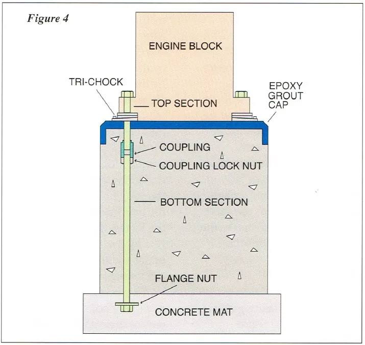
Along with the free length/sleeve concept has come another practice, sometimes applicable, of making an anchor bolt in two pieces, connecting them with a coupling nut. (See Figure 4). The bolting system is cast or grouted into the concrete block.
The lower section is long enough to allow the full strength of the bolt to be used before a shear cone pullout in the concrete can occur. A shallow anchor bolt would pull out of the concrete well before the ultimate strength of the bolt is reached.
The top section usually is longer than the free length required. If there is an anchor bolt failure, it will be in the top section and can be replaced by unscrewing the broken section from the coupling nut. Two-piece anchor bolts make equipment installation easier and are usually used if a load monitor like the RotaBolt™ is included in the system.
Anchor Bolts are Post-Tensioners
As the usage of twopiece anchor bolts has become common practice, this has led to a newer innovation in the new concrete foundation design. (See Figure 4). The value in post-tensioning the concrete foundation, including the interface between the block and the mat, has been recognized by civil engineers.
More recently, this has been enhanced by using the anchor bolt as a post-tension member also. This is accomplished by extending the length of the bottom section so it is long enough to be anchored in the concrete mat underneath the concrete foundation.
Keeping cyclic tensile forces from fatiguing the concrete is just now being recognized for its importance, and post-tensioning the foundation can help in this regard. Additionally, extending the anchor bolts into the mat will help prevent movement at the foundation mat interface when there is a large overturning moment from the action of the machine. A third advantage is that an anchor bolt terminating in the mat is more likely to remain truly vertical when concrete for the block is poured, even if the rebar cage shifts during placement. The minimal extra cost for long anchor bolts is money well spent.
Upgrading Anchor Bolts
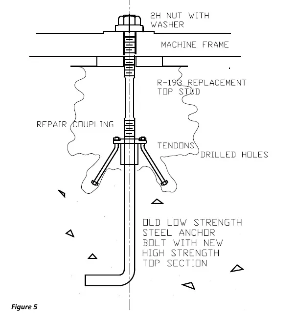
More often, anchor bolts break from too little tightening than too much. There are times, though, when the original design clamping force needs to be increased. The original anchor bolts, such as those made of merchant grade steel, may not have enough tensile load carrying capacity. These bolts can usually be upgraded in much the same way as anchor bolts are repaired, by using a high strength, 4140, heat treated coupling nut and new top bolt section. However, since the top section is stronger than the old steel, additional anchoring for the bottom section, after cutting it off and threading it for the coupling nut, can be added by using a flange as part of the coupling nut. This flange has holes for B7 tendons which angle off into drilled holes in the concrete and are fixed in place with epoxy grout as is the flange itself. (See Figure 5).
This repair method is easier to make than trying to dig out and replace the entire anchor bolt, particularly on bolts in the center of a large block. The new top section should be long enough to have proper free length, and with the bottom anchored properly its full load capacity can now be used.
Anchor bolts are indeed a complex item with a very simple purpose.
Additional information on anchor bolts can be found in the following technical society publications:
- “Anchorage Design for Petrochemical Facilities” Available from the ASCE Library
- “Section 4.4.2 – Foundations for Dynamic Equipment” ACI 351.3R-04
Home > Newsletters > Anchor Bolts - The Forgotten Connection

